Suspended Loads: Safer Lifting and Travel with Hoists
Alessandro Prastaro
Health & Safety
Manufacturing
Selecting lifting accessories, understanding load capacity and using protective devices effectively.
Moving a suspended load requires control of the complete lifting system: supporting structure, trolley, hoist, hook, accessories, attachment points and load. A suitable hoist alone does not make the operation safe.
This proposed best practice combines load assessment, appropriate accessories, pre-use inspection and protective functions. It addresses material handling, not lifting people.
START WITH THE LOAD
Establish weight, centre of gravity, dimensions, lifting points and structural integrity. Include below-hook accessories when checking the load imposed on the hoist. An 800 kg component with a 100 kg lifting beam and 20 kg of other accessories imposes a nominal suspended mass of 920 kg. Verify the actual configuration, operating conditions and manufacturer’s limits.
Plan the route and landing area, keep people outside the lifting zone and use competent operators and slingers. Start with a controlled trial lift just clear of the support to check balance and attachment. [1]
SELECT ACCESSORIES FOR THE LOAD
• Machinery with engineered lifting points: rated chain or wire-rope slings, shackles and suitable lifting eyes. Check point capacity, permitted load direction, sling angle and centre of gravity.
• Painted or delicate components: suitable textile webbing or round slings. Check edge protection, cutting risk, chemical compatibility and temperature.
• Long beams, pipes or flexible assemblies: engineered lifting or spreader beam with suitable slings. Check beam self-weight, span, stability and load distribution.
• Steel plate: purpose-designed plate clamps or approved magnetic/vacuum devices. Check orientation, thickness, surface condition and device-specific operating limits.
• Coils and cylindrical loads: purpose-designed coil hooks, grabs or cradles. Check dimensions, retention, balance and permitted orientation.
For plate clamps, verify maximum capacity and any minimum load needed for reliable gripping. Magnets and vacuum devices require assessment of material, surface and loss-of-holding-force risks. [2]
Use the sling identification and manufacturer’s tables for the actual hitch and conditions. Protect textile slings against damaging edges. Inspect chain and wire-rope slings and use compatible fittings. Never substitute general-purpose chain or transport lashing straps for rated lifting accessories.
Source: https://www.osha.gov/laws-regs/regulations/standardnumber/1910/1910.184
THREE DIFFERENT CALCULATIONS
1. WORKING LOAD LIMIT (WLL)
The manufacturer’s rated working capacity applies under specified conditions. The permitted capacity of the arrangement depends on its weakest applicable component and configuration. A 2-tonne hoist does not make a 1-tonne sling suitable for a 1.5-tonne load.
2. DESIGN FACTOR / SAFETY COEFFICIENT
Design factor = minimum breaking force ÷ rated working force.
Use consistent units. A component with minimum breaking force 40 kN and rated working force 10 kN has a design factor of 4. This illustrates a design relationship, not a method for assigning a homemade device its own WLL. Use certified manufacturer ratings. Crosby publishes Grade 100 chain-sling ratings based on 4:1; do not assume this value for every accessory.
Source: https://www.thecrosbygroup.com/html/en/pdf/pgs/261.pdf
The design factor is not spare capacity. A proof-test load is not an operating limit.
3. SLING-LEG TENSION
For an ideal, static, symmetrical two-leg arrangement with equal sharing:
T = W ÷ (2 × cos β)
T = tensile force in each leg; W = total force supported by the two legs; β = each leg’s angle FROM VERTICAL.
For a supported mass of 1,000 kg, W ≈ 9.81 kN:
0°: 4.91 kN per leg
30°: 5.66 kN per leg
45°: 6.94 kN per leg
60°: 9.81 kN per leg
Wider angles increase tension and horizontal forces at attachment points. These figures illustrate statics: selection must follow rated angle bands and manufacturer tables. Do not assume equal sharing for asymmetric loads, or that four legs each carry one quarter. Choker hitches and other configurations can require capacity reductions. [3]
OVERLOAD PROTECTION
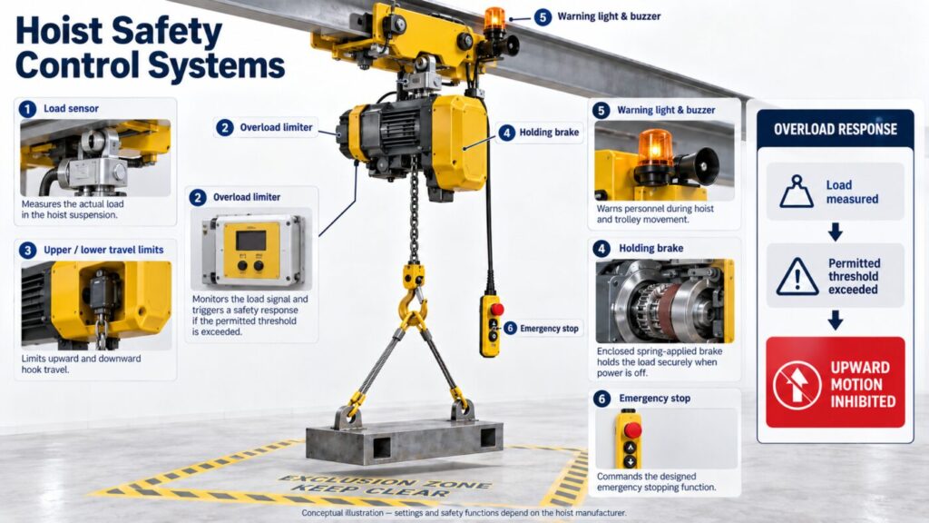
An indicator displays or signals load; a limiter acts to prevent unsafe operation. With electronic sensing, the intended sequence is:
Load measurement → validated comparison with permitted threshold → inhibition of further upward movement when exceeded.
The manufacturer defines threshold, tolerances, response and recovery. Do not assume tripping at exactly 100% of nameplate capacity.
Some hoists use a friction clutch instead of directly measuring weight. Demag describes monitored slipping-clutch protection and a brake arrangement intended to retain the load. A clutch is not a weighing instrument.
Source: https://www.demagcranes.com/en/products/hoist-units/chain-hoists/dc-com-chain-hoist
The hoist limiter may not detect excessive tension in one sling leg or overload of a lower-rated accessory.
LIMIT SWITCHES AND MECHANICAL PROTECTION
Upper and lower limits help prevent excessive hook travel. KITO documents upper/lower switches and friction-clutch overload protection on its EQ hoist.
Source: https://kito.co.jp/en/products/eh/EQ
Do not use the upper hoist limit as the normal stopping control. Where required, an independent final limit remains a separate protective layer. Follow manufacturer testing procedures; do not improvise overload tests during pre-use checks. [4]
Assess the holding brake, emergency stop, hook retention, chain guide and collection arrangement. Use only manufacturer-approved chain components and modifications.
LIGHTS, BUZZERS AND TRAVEL CONTROLS
For a travelling hoist, assess warning lights, horn/buzzer/siren, trolley and bridge travel limits, and motor thermal protection. Konecranes also describes sway control and shock-load prevention for compatible systems. [5]
Warnings must be distinguishable in actual lighting and noise conditions. They supplement exclusion zones and safe routes; they do not authorise travel over people.
Additional options include projected floor warning lights and side-pull prevention. Konecranes describes a system stopping hoisting when the load is not directly beneath the hoist. Check suitability for the installation.
Sources:
https://portal.konecranes.com/amer/en/category/SP00005099/SP00015499
https://marketing.konecranes.com/acton/media/35190/side-pull-prevention
PRE-USE AND OPERATING CHECKLIST
1. Confirm weight, centre of gravity and suitable lifting points.
2. Verify capacities for the complete arrangement and actual sling configuration.
3. Inspect chains, slings, hooks, fittings and identification; quarantine defective equipment.
4. Check controls and protective functions using the manufacturer’s procedure.
5. Clear the route and landing area; agree communication and signals.
6. Perform a controlled initial lift to confirm balance and secure attachment.
During movement, avoid shock loading and side pulling. Keep the load at a suitable minimum travel height, maintain visibility and keep everyone clear. Land it securely before releasing accessories.
Record equipment IDs, defects, corrective actions and inspection status. Pre-use checks complement periodic examination and maintenance; they do not replace them.
Source: https://www.hse.gov.uk/pubns/indg474.pdf
The intended outcome is a documented lifting arrangement, appropriate accessories and verified protective functions before operation. No reduction in incidents or equipment failures is claimed without application data.
Supporting references in Reusable materials:
[1] HSE — Safe lifting by machine.
[2] HSE — Handling steel and metal stock.
[3] Crosby — Rigging information.
[4] OSHA — Overhead and gantry cranes.
[5] Konecranes — Crane safety improvements.
Additional source URLs accompany the relevant sections.
This is a proposed practice, not a validated lifting plan for a particular load. Equipment selection, protective-device settings and modifications require competent assessment using the specific manufacturer’s documentation.
HSE and OSHA references provide useful technical guidance; their legal requirements apply within their respective jurisdictions.
Do not use the design factor as additional working capacity. An overload limiter does not replace correct rigging or automatically protect lower-rated accessories.
The AI-generated illustration is conceptual, not an exact product photograph, wiring diagram or approved equipment design. Settings and safety functions depend on the hoist manufacturer.
https://www.hse.gov.uk/work-equipment-machinery/lift-equipment.htm
https://www.hse.gov.uk/pubns/priced/hsg246.pdf
https://www.thecrosbygroup.com/wp-content/uploads/catalog/2016/en-US/473.pdf
https://www.osha.gov/laws-regs/regulations/standardnumber/1910/1910.179
https://www.konecranes.com/sites/default/files/2019-08/Safety_Whitepaper_Aug2019_Konecranes.pdf