Safety Before Start-up: Checking Machine Safety Devices
Alessandro Prastaro
Health & Safety
Manufacturing
Pre-use inspection, enforced functional testing and Performance Level: comparing Siemens and Pilz.
A closed guard and a green indicator do not, by themselves, demonstrate that a protective device works correctly. Pre-use inspection should combine visual checks with manufacturer-specified functional tests, performed without exposing anyone to hazards.
The proposed best practice links these checks to machine enablement: hazardous functions remain inhibited until all required tests have been completed successfully.
This is a proposed engineering practice based on manufacturer documentation, not a report of measured results from a specific installation.
THE SIEMENS APPROACH: FAIL-SAFE INPUTS AND SAFETY LOGIC
A relevant example is the SIMATIC ET 200SP F-DI 8×24 VDC HF, part number 6ES7136-6BA01-0CA0. This is a fail-safe digital input module used with a fail-safe CPU and safety program, not a standalone PLC.
Its eight inputs can be paired to evaluate four dual-channel signals. Siemens documents applications up to SIL 3 / Category 4 / PL e, subject to the specified sensor, wiring and diagnostic requirements. The module’s capability does not automatically establish the Performance Level of the complete machine safety function. [1]
The complete safety chain includes:
Protective device → safe inputs → fail-safe logic → safe outputs → final elements that stop or prevent hazardous movement.
“If the signal is missing, the machine cannot operate” should therefore be understood precisely: loss of a required safety permissive must prevent hazardous operation or initiate the defined safe response. This does not necessarily mean switching off every machine service.
ENFORCING A TEST BEFORE OPERATION
Siemens’ SFDOOR safety-door monitoring function provides the OPEN_NEC parameter. When set to 1, it requires the guard to be detected as fully open and then closed following fail-safe system start-up before an enable can be issued. ACK_NEC can additionally require manual acknowledgement.
This checks an actual input transition rather than simply accepting a static “guard closed” signal. Diagnostic information supplied to the operator interface must not be treated as a fail-safe control signal. [2]
A system start-up test and a test before every shift or use are different requirements. A machine may remain powered between shifts. If the risk assessment and manufacturer’s instructions require testing at each shift, that recurrence must be explicitly designed and validated. “Enforced testing” means making enablement conditional on a successful test; it does not imply a universal requirement to open every guard before every production cycle.
COMPARING THE PILZ APPROACH
The Pilz PNOZ s4 safety relay provides a start-up test mode: after power is applied, a guard that is initially closed must be opened and closed again. Its manual also distinguishes dual-channel operation with and without detection of shorts across contacts. Reset behaviour requires careful consideration: completing the test must not permit an unexpected hazardous restart. [3]
For applications involving multiple protective devices and more complex logic, PNOZmulti 2 is the more relevant comparison with a programmable Siemens safety system. Pilz specifies applications up to PL e / SIL CL 3, depending on the application and configuration.
Source: https://www.pilz.com/en-INT/products/small-controllers/configurable-control-systems/pnozmulti-2-controllers
Applications to consider:
• Siemens fail-safe CPU with ET 200SP F-I/O: safety integrated into machine or production-line automation.
• Pilz PNOZ s4: a limited set of functions managed by a safety relay.
• Pilz PNOZmulti 2: multiple protective devices and configurable safety logic.
Selection should follow the required safety functions and their validation, rather than brand preference alone.
DUAL-CHANNEL DEVICES AND PERFORMANCE LEVEL e
Dual-channel architecture introduces redundancy, but two channels do not automatically achieve PL e. Common-cause failures, unsuitable wiring or inadequate diagnostics can compromise both paths.
Assessment covers the complete safety function, from the sensor to the final control element. First determine the required Performance Level, PLr, from the risk assessment. Then establish the achieved PL, considering:
• Architecture category.
• Component reliability, using MTTFd or relevant reliability data.
• Average diagnostic coverage, DCavg.
• Measures against common-cause failures, CCF.
• Software, systematic failures and operating conditions.
Performance Levels range from PL a to PL e, with increasing requirements. For PL e, the average frequency of dangerous failure must fall within 10⁻⁸ ≤ PFHᴅ < 10⁻⁷ per hour. Meeting that numerical range alone is insufficient: the other applicable requirements must also be satisfied. Category and Performance Level are not interchangeable. [4]
1. INSPECT. Check the condition, mounting and absence of obvious tampering on the devices included in the procedure.
2. TEST. Operate each protective device according to the manufacturer’s instructions, under controlled conditions and without entering hazardous areas.
3. VERIFY THE RESPONSE. Check the actual safety-function response, not just a message on the operator panel.
4. MANAGE FAILURES. Keep the affected operation inhibited and follow the corrective-action procedure. Do not bypass the protection.
5. RE-ENABLE SAFELY. Complete the specified reset procedure, then issue a separate start command.
6. RECORD THE OUTCOME. Capture the machine identifier, devices tested, operator, date, results and any defects.
The expected benefit is a more systematic, traceable check before machine enablement. Any claimed reduction in failures or incidents should be supported by evidence from the actual application.
No measured improvement or validated Performance Level is claimed for a specific machine in this contribution.
The numbered supporting documents in Reusable materials are:
[1] Siemens F-DI equipment manual.
[2] Siemens SFDOOR documentation.
[3] Pilz PNOZ s4 operating manual.
[4] IFA Report 1/2025 on functional safety of machine controls.
[5] ISO 13849-2 — Validation.
This workflow must be adapted and validated for the specific machine. It is not a universal test procedure.
Pre-use inspection does not replace design validation, periodic testing or maintenance. Validation must include analysis and testing of the specified safety functions, achieved category and Performance Level. [5]
A successful start-up test does not, by itself, prove that the complete safety function achieves PL e. The full sensor–logic–actuator chain, failure behaviour and relevant operating conditions must be assessed.
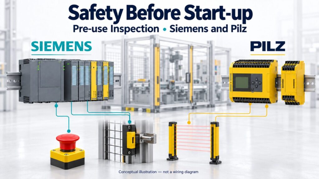
The accompanying AI-generated illustration is conceptual. It is not an exact product photograph, electrical wiring diagram or certified design.
https://cache.industry.siemens.com/dl/files/402/109803402/att_1083697/v1/et200sp_f-di_8x24vdc_hf_manual_en-US_en-US.pdf
https://docs.tia.siemens.cloud/r/en-us/v21/step-7-safety-v21-instructions/safety-functions/sfdoor-safety-door-monitoring-step-7-safety-v21?contentId=YwsCw7YICEaQe26~DALIzA
https://www.pilz.com/download/open/PNOZ_s4_Operat_Man_21396-EN-17.pdf
https://publikationen.dguv.de/widgets/pdf/download/article/5091
https://www.iso.org/standard/53640.html